1.1.1 - Sound Propagation Principles
Sound Propagation Principles
What you'll learn
- INSTRUMENTATION: Physics and image formation -> Sound propagation basics — choose the correct relationship among frequency, wavelength, and propagation speed.
- INSTRUMENTATION: Physics and image formation -> Tissue interaction logic — decide when reflection, scattering, refraction, or attenuation best explains a sonographic appearance.
- INSTRUMENTATION: Scanning technique -> Best next image-optimization step — identify which propagation principle explains weak penetration, shadowing, or poor border definition.
- INSTRUMENTATION: Safety and quality -> Prudent output use — connect propagation behavior to ALARA-minded sonographer decisions.
- INSTRUMENTATION: Protocol reasoning -> Scope-appropriate escalation — recognize when to document technical limitations and notify the interpreting physician per protocol.
- Domain: Instrumentation and image optimization → Physics and image formation → high emphasis
- Domain: Scanning protocols → Image acquisition choices → medium emphasis
- Domain: Safety and quality concepts → Bioeffects-aware scanning behavior → medium emphasis
Why it matters
- ARDMS items often hide physics inside an image-quality problem: the stem asks for the best next step, but the real test is whether you know which propagation rule is being violated.
- OB/GYN scanning depends on rapid probe and setting choices across deep pelvis, early pregnancy, body habitus variation, and technically limited exams.
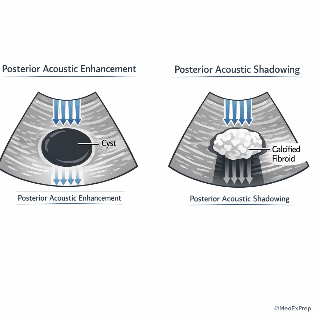
- Propagation principles explain why fluid enhances, calcification shadows, oblique interfaces lose echoes, and deep targets fade.
- Strong physics reasoning prevents unsafe or ineffective habits such as increasing output when a better answer is changing frequency, angle, focal placement, or approach.
Key Terms & Must-Know Facts
1.1.1.1 Key terms
- Propagation speed — how fast sound travels in a medium; in soft tissue, assumed about 1540 m/s.
- Frequency — cycles per second; higher frequency improves detail but reduces penetration.
- Wavelength — physical length of one cycle; inversely related to frequency.
- Period — time for one cycle; inverse of frequency.
- Amplitude — strength of the wave; related to echo magnitude and signal intensity.
- Acoustic impedance — resistance to sound transmission in a medium; mismatch drives reflection.
- Reflection — sound returning from an interface.
- Scattering — redirection of sound in many directions from small or irregular reflectors.
- Refraction — bending of the beam when speed changes across an oblique boundary.
- Attenuation — loss of sound intensity with depth from absorption, reflection, and scattering.
- Absorption — conversion of sound energy to heat.
- Specular reflector — large smooth interface; angle-dependent bright echo.
- Diffuse reflector — rough/small interface; returns weaker echoes over broader angles.
- Acoustic enhancement — increased through-transmission behind low-attenuation fluid.
- Acoustic shadowing — signal drop behind highly attenuating or strongly reflecting structures.
1.1.1.2 Must-know facts
- Soft-tissue imaging systems assume sound speed of 1540 m/s.
- \( c = f\lambda \) links propagation speed, frequency, and wavelength.
- In a given medium, speed stays constant; changing frequency changes wavelength, not speed.
- Higher frequency means shorter wavelength.
- Shorter wavelength supports better axial detail; the upcoming lesson expands this tradeoff.
- Large impedance mismatch causes stronger reflection.
- A smooth interface is brightest when the beam is close to perpendicular.
- Fluid typically causes posterior enhancement because attenuation is low.
- Bone, calcification, and gas commonly cause strong shadowing or dropout.
- Refraction is more likely at an oblique boundary between media with different propagation speeds.
| Parameter | What changes it | Key relationship | Exam use |
|---|---|---|---|
| Propagation speed | Medium only | Approx. 1540 m/s in soft tissue | Assumed by system for range calculations |
| Frequency | Source/transducer | Inverse to period | Probe selection and penetration/detail tradeoff |
| Wavelength | Frequency and medium | \( \lambda = c/f \) | Foundation for resolution logic |
| Amplitude | Power and attenuation | Related to signal strength | Echo brightness and weakening with depth |
| Attenuation | Frequency, depth, tissue properties | Increases with depth and higher frequency | Explains poor deep visualization |
Core content
1.1.1.3 Foundational relationships: speed, frequency, wavelength, and period
A Explanation
A common exam conflict is deciding whether a weak or blurry image is caused by frequency choice or by a misunderstanding of what changes sound speed. The resolving rule is simple: in a given medium, propagation speed is fixed by the medium, not by the probe frequency. If frequency increases in the same tissue, wavelength shortens. That is why shorter wavelengths support better detail but usually less penetration. WHY THIS IS TESTED: stems often present a deep pelvic target, an endocavitary-versus-transabdominal choice, or an equation item that tries to bait you into saying that higher frequency travels faster.
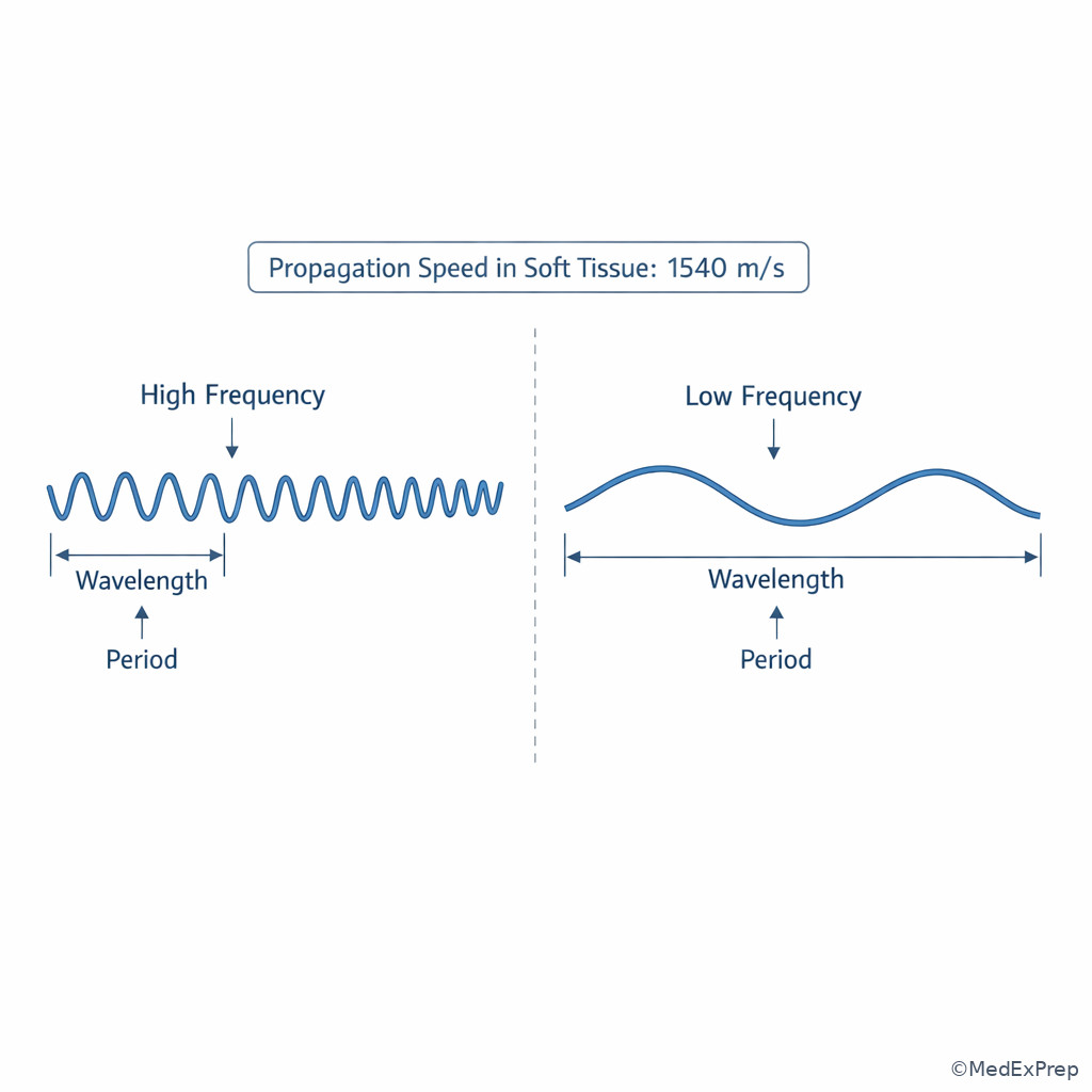
For ARDMS-style reasoning, separate the variables. The transducer sets frequency. The tissue sets speed. The machine assumes an average soft-tissue speed to place echoes in depth correctly. Period is just the time for one cycle and falls as frequency rises. When you see a formula question, the governing relationship is \( c=f\lambda \). If the medium is unchanged, \( c \) is constant; therefore increasing \( f \) decreases \( \lambda \). See Fig 1.
Exam takeaway: In the same tissue, frequency changes wavelength, while the medium determines propagation speed.
flowchart TD
A[Need to explain image change] --> B{Did the medium change?}
B -- No --> C[Speed stays same]
C --> D{Did frequency increase?}
D -- Yes --> E[Wavelength decreases]
D -- No --> F[Wavelength increases]
B -- Yes --> G[Speed may change]
G --> H[Possible timing/path effects] Exam takeaway: Solve basic physics stems by identifying which variable belongs to the probe and which belongs to the tissue.
Exam takeaway: Visualizing wave length and cycle spacing helps you reject the common mistake that higher frequency travels faster in the same tissue.
B Worked example
A 29-year-old gravida 1 para 0 patient with obesity and a retroverted uterus presents for early pregnancy sonography. The sonographer begins transabdominally and the gestational sac is poorly seen deep in the pelvis. A trainee states that using a higher-frequency probe will make the sound travel faster and reach the sac better. There is also mild bladder underfilling, which is a distracting technical limitation. The most appropriate reasoning chain is: identify task — explain the propagation principle; extract key facts — same tissue assumption, deep target, higher frequency being proposed; apply rule — speed is set by tissue, not probe frequency; higher frequency shortens wavelength but generally penetrates less; eliminate distractors — faster propagation is false, and underfilled bladder matters for approach but does not change the physics rule; verify — a lower-frequency transabdominal option or transvaginal approach better addresses depth/location.
C Exam trap
D Checkpoint
Question: During a pelvic scan, the sonographer switches to a higher-frequency transducer while imaging the same tissue. Which change is most likely?
- Propagation speed increases because the beam cycles more often.
- Wavelength decreases while propagation speed in that tissue remains unchanged.
- Period increases because the pulse is more tightly packed.
- Acoustic impedance decreases because the probe frequency is higher.
Correct answer: B.
- A: Tempting because “more cycles” sounds like “faster travel,” but speed depends on medium, not frequency.
- B: Correct because in the same tissue \( c \) stays constant, so higher \( f \) means lower \( \lambda \).
- C: Tempting because period and wavelength are often mixed up, but period decreases as frequency increases.
- D: Tempting because impedance sounds like a machine setting, but impedance is a property of tissue, not probe frequency.
1.1.1.4 Tissue interaction: reflection, scattering, refraction, and attenuation
A Explanation
Another common decision conflict is choosing which interaction best explains the image: reflection from a smooth interface, scattering from small irregular structures, refraction from beam bending across an oblique speed boundary, or attenuation as overall energy loss with depth. The single resolving rule is to ask, “Did the sound mainly bounce back, spread out, bend, or fade?” WHY THIS IS TESTED: exam items frequently describe a grayscale pattern without naming the physics principle.
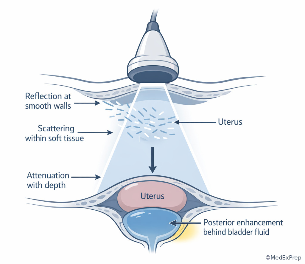
Reflection is strongest at smooth, larger interfaces and is highly angle dependent. A specular reflector, such as a smooth wall or diaphragm-like boundary, sends the echo back best when the beam is nearly perpendicular. Scattering is more typical of small or rough structures, producing echoes in multiple directions; this helps create tissue texture rather than one sharp interface. Refraction requires an oblique incidence angle and different propagation speeds across the boundary; the beam bends and may misplace structures or create edge-related artifacts. Attenuation is the cumulative weakening of the beam with depth from absorption, reflection, and scattering. See Fig 2 and Fig 3.
Exam takeaway: Sort image findings by whether sound bounced back, spread out, bent, or weakened with depth.
flowchart TD
A[Observed sonographic effect] --> B{Main behavior?}
B -- Bright return from smooth border --> C[Reflection]
B -- Many weak echoes from irregular small targets --> D[Scattering]
B -- Beam changes direction at oblique boundary --> E[Refraction]
B -- Signal weakens with depth --> F[Attenuation]
C --> G[Angle critical]
D --> H[Texture formation]
E --> I[Possible edge artifact]
F --> J[Poor deep visualization] Exam takeaway: Angle dependence points to reflection, diffuse texture points to scattering, and beam bending at an oblique interface suggests refraction.
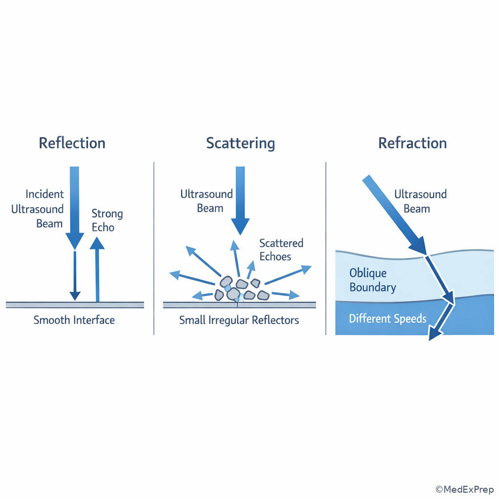
Exam takeaway: Name the dominant beam behavior first, then tie it to the grayscale pattern.
Exam takeaway: Distinguishing bounce, bend, and fade helps you choose the best next scanning adjustment rather than guessing settings changes.
B Worked example
A 37-year-old patient with prior cesarean delivery, fibroids, and a history of pelvic inflammatory disease presents for transabdominal pelvic sonography. A smooth fluid-filled bladder is seen anterior to the uterus. Deep to the bladder, the tissue appears brighter than adjacent regions. A distracting clue is mild bowel gas at the left adnexa. The reasoning chain is: identify task — explain why echoes are brighter posterior to fluid; extract key facts — anechoic fluid, brighter tissue deep to it, no need to invoke probe malfunction; apply rule — low attenuation through fluid causes posterior acoustic enhancement; eliminate distractors — shadowing would darken, refraction would misplace or split edges, scattering explains texture but not the bright through-transmission pattern; verify — the finding is classic enhancement, not an equipment error.
C Exam trap
D Checkpoint
Question: A smooth structure is brightest only when the beam strikes it near 90 degrees. Which sound-tissue interaction is being tested?
- Specular reflection
- Diffuse scattering
- Absorption
- Refraction
Correct answer: A.
- A: Correct because smooth interfaces are angle dependent and return the strongest echo when insonated perpendicularly.
- B: Tempting because many tissues produce texture, but scattering is not the classic “best at 90 degrees” phenomenon.
- C: Tempting because energy is lost in tissue, but absorption does not explain angle-dependent bright echoes.
- D: Tempting because angle matters in refraction too, but refraction describes bending across a boundary, not maximal echo return to the transducer.
- The assumed average propagation speed in soft tissue is 1540 m/s.
- True or False: In the same tissue, increasing frequency increases sound speed. False.
- Name the 3 key interaction ideas most often confused in stems: reflection, refraction, attenuation.
1.1.1.5 Impedance mismatch and angle of incidence: why some interfaces are bright and others disappear
A Explanation
In practice, sonographers must often choose between blaming a faint border on poor machine settings versus an unfavorable insonation angle. The decisive rule is this: echo strength from a smooth boundary depends heavily on both impedance mismatch and angle of incidence. A large impedance difference increases reflected energy, but if the beam is not directed back toward the transducer, the interface may still look weak. WHY THIS IS TESTED: ARDMS stems like to describe a wall or membrane that “disappears” until the probe is rocked or angled.
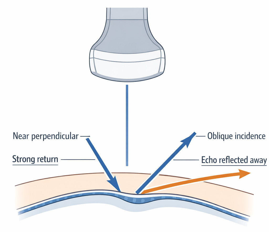
Acoustic impedance is determined by tissue properties, classically density and propagation speed. You do not need to perform calculations on most registry items; you need the logic. Similar tissues produce less reflection at the boundary; dissimilar tissues produce more. However, strong mismatch alone is not enough for a bright returning echo if the sound is reflected away from the transducer. This is especially relevant for smooth curved structures, sac margins, cyst walls, and fetal or pelvic boundaries where probe pressure or angle changes make the structure suddenly appear clearer. See Fig 4.
Exam takeaway: A border can be real yet look weak if the beam is not directed close to perpendicular to the interface.
flowchart LR
A[Interface between tissues] --> B{Large impedance mismatch?}
B -- Yes --> C[Potential for strong reflection]
B -- No --> D[Weak reflection expected]
C --> E{Beam near perpendicular?}
E -- Yes --> F[Strong returning echo]
E -- No --> G[Echo reflected away]
D --> H[Low-contrast border] Exam takeaway: Before blaming gain, ask whether the interface is being struck at a useful angle.
Exam takeaway: A small probe angulation change can convert a missed border into a strong echo when the interface is specular.
B Worked example
A 34-year-old patient undergoing infertility monitoring has a normal BMI, a small uterine fibroid, and mild pelvic tenderness. During transvaginal imaging, the endometrial-myometrial interface appears crisp in one plane but poorly defined in a slightly different sweep. A tempting wrong clue is that the user recently decreased overall gain. The reasoning chain is: identify task — determine why border conspicuity varies with probe movement; extract key facts — same structure, small sweep change, crisp in one angle but not another; apply rule — specular interfaces are angle dependent, so a near-perpendicular beam returns stronger echoes; eliminate distractors — gain affects the whole field rather than selectively improving one border in one angle; verify — slight repositioning restores the interface.
C Exam trap
D Checkpoint
Question: Which single factor best explains why a smooth cyst wall may appear much brighter after a slight probe tilt, even when the machine settings are unchanged?
- Reduced attenuation from the wall itself
- Improved specular reflection due to a more perpendicular angle
- Higher propagation speed created by probe tilt
- Increased scattering from the fluid within the cyst
Correct answer: B.
- A: Tempting because attenuation affects brightness, but a slight tilt does not meaningfully change attenuation through the wall.
- B: Correct because specular interfaces return stronger echoes when insonated near perpendicular.
- C: Tempting only if angle and speed are confused; probe tilt does not alter tissue propagation speed.
- D: Tempting because fluid is involved, but simple fluid produces little scattering and the wall, not the fluid, explains the changing bright line.
1.1.1.6 Attenuation in clinical scanning: depth, tissue type, and frequency choice
A Explanation
When the question asks for the best next sonographer action in a deep pelvis or technically difficult patient, the conflict is usually: turn up output/gain versus change frequency, approach, or window. The resolving rule is that attenuation increases with depth and generally with higher frequency. WHY THIS IS TESTED: image-optimization questions frequently dress up attenuation as an anatomy or workflow problem.
Attenuation is not a single event; it is cumulative loss from absorption, scattering, and reflection. In clinical OB/GYN scanning, deep pelvic structures, obesity, overlying bowel gas, and long sound paths can all reduce useful returning echoes. Increasing gain may brighten noise and near field without truly improving deep information. Often the higher-yield solution is selecting a lower-frequency transducer for transabdominal depth, switching to transvaginal imaging for a closer target, adjusting patient position, or using the bladder as an acoustic window when appropriate. See Fig 5. The next lesson on resolution and penetration tradeoffs expands this choice in greater detail; this lesson establishes the propagation reason behind it.
Exam takeaway: Deep targets lose signal with path length, so the best fix is often approach or frequency selection rather than simply increasing brightness controls.
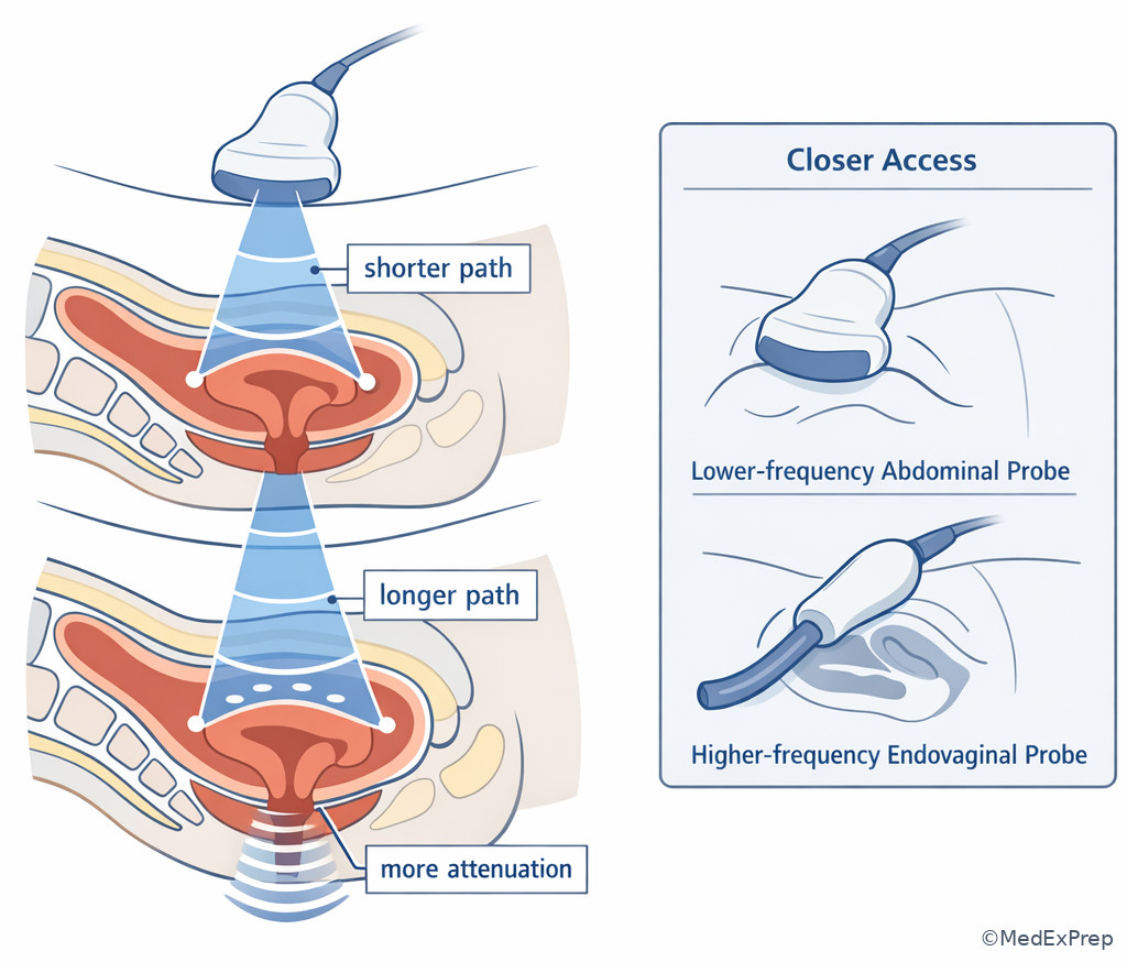
Exam takeaway: Treat poor deep visualization as a propagation problem first, not merely a brightness problem.
Exam takeaway: Low attenuation through fluid brightens tissue beyond it, while high attenuation by calcified or gaseous structures darkens tissue behind it.
B Worked example
A 41-year-old patient with obesity, prior abdominal surgery, and irregular bleeding presents for pelvic sonography. Transabdominal imaging shows a deep retroverted uterus with low-level echoes and poor far-field detail. A distracting clue is that overall gain seems slightly low. The trainee suggests maximizing output power first. The reasoning chain is: identify task — choose the best next sonographer action; extract key facts — deep target, long path length, body habitus, retroverted uterus; apply rule — attenuation increases with depth and higher frequency, so the better strategy is shortening the path with transvaginal imaging or selecting more appropriate frequency/approach; eliminate distractors — gain alone may brighten noise, and indiscriminate output increase conflicts with prudent ALARA use; verify — the closer endovaginal approach better overcomes attenuation by reducing travel distance.
C Exam trap
D Checkpoint
Question: A deep pelvic structure is poorly visualized on transabdominal imaging in a patient with increased body habitus. Which option best addresses the main propagation problem?
- Increase frequency to shorten wavelength and improve penetration
- Use a closer approach or lower-frequency option because attenuation increases with depth
- Increase acoustic impedance by selecting a different preset
- Assume the sound speed is reduced and repeat the same scan without changes
Correct answer: B.
- A: Tempting because shorter wavelength can improve detail, but higher frequency generally worsens penetration.
- B: Correct because a shorter path or lower frequency directly counters depth-related attenuation.
- C: Tempting because the preset changes machine behavior, but it does not change tissue impedance.
- D: Tempting only if speed assumptions are misunderstood; repeating without addressing attenuation is not the best response.
- The most common reason deep structures fade is attenuation with depth.
- True or False: Increasing frequency usually improves penetration. False.
- Name two efficient fixes for a deep poorly seen pelvic target: lower frequency and shorter path/closer approach.
1.1.1.7 Integration: translating propagation physics into best next sonographer actions
A Explanation
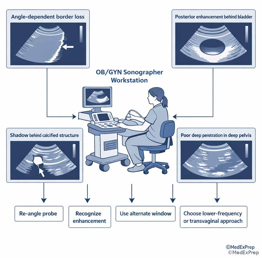
Foundational physics becomes testable only when tied to action. The final conflict is not “What is attenuation?” but “What should the sonographer do next?” The rule is to match the image problem to the propagation mechanism, then choose the smallest effective correction within scope. WHY THIS IS TESTED: registry items rarely reward physics memorization alone; they reward correct protocol-based application.
If a smooth border appears and disappears with angle, adjust insonation before changing overall gain. If a fluid-filled structure causes brightness distal to it, recognize enhancement and avoid mislabeling it as machine overgain. If a dense or highly attenuating structure causes dropout behind it, think shadowing. If a deep structure is weak, solve depth-related attenuation with approach and frequency logic. If a finding remains concerning or technically limited after appropriate optimization, document objectively and notify the interpreting physician per protocol rather than overcalling or reassuring the patient. See Fig 6.
Exam takeaway: Match the observed pattern to the underlying beam behavior, then choose an optimization step before escalating.
flowchart TD
A[Image problem noted] --> B{Pattern?}
B -- Border changes with tilt --> C[Angle-dependent reflection]
B -- Brightness behind fluid --> D[Enhancement]
B -- Dark band behind dense/gas structure --> E[Shadowing]
B -- Deep target weak --> F[Attenuation with depth]
C --> G[Re-angle probe]
D --> H[Recognize normal through-transmission]
E --> I[Use alternate window if needed]
F --> J[Change approach or frequency]
G --> K[Document optimized view]
H --> K
I --> K
J --> K
K --> L{Critical anatomy still limited?}
L -- Yes --> M[Notify per protocol]
L -- No --> N[Continue exam] Exam takeaway: Good registry answers fix the image problem first, then document and escalate when needed.
Exam takeaway: Practical registry questions reward choosing the lowest-risk, highest-yield adjustment that matches the underlying physics.
B Worked example
A 26-year-old patient with a history of endometriosis and a current positive pregnancy test presents for early first-trimester evaluation. Transabdominal views show a deep pelvis and weak visualization of the gestational sac region. A bright band is present behind the bladder, and one bowel gas pocket causes lateral dropout. A tempting but wrong clue is that the patient is anxious and asks whether the sonographer can tell her everything is normal. The reasoning chain is: identify task — best next sonographer action; extract key facts — deep target, enhancement behind fluid, separate bowel gas limitation, patient request outside interpretive scope; apply rule — deep weakness is attenuation/path related, so choose a closer transvaginal approach if indicated and per protocol; eliminate distractors — enhancement is not pathology, gas shadowing is localized not global, reassuring the patient diagnostically is outside role; verify — obtain better views, document findings, and communicate significant concerns per policy.
C Exam trap
D Checkpoint
Question: Which option best reflects registry-level application of sound propagation principles during an OB/GYN ultrasound exam?
- When a smooth border fades with angulation changes, first document nonvisualization and end the exam.
- When posterior enhancement is seen behind fluid, increase output power because the beam is too weak.
- When a deep target is poorly seen, choose a closer or lower-frequency approach before indiscriminately increasing power.
- When an interface is angle dependent, conclude the structure is pathologic because it is inconsistent across planes.
Correct answer: C.
- A: Tempting because documentation matters, but optimization should come before declaring nonvisualization.
- B: Tempting because the image looks bright/dark in places, but enhancement is expected through-transmission, not a signal to raise power.
- C: Correct because it addresses attenuation directly and aligns with prudent sonographer workflow.
- D: Tempting because inconsistency raises suspicion, but angle-dependent interfaces can be normal physics rather than pathology.
Exam Traps & Differentiators
Most common wrong answer and why: “Increase gain” or “increase output power” is tempting because many propagation problems present as a dark or weak image. The better answer is usually the one that addresses the actual mechanism: angle for specular reflection, approach/frequency for attenuation, recognition rather than correction for enhancement.
| Looks similar | But isn't | Discriminator | Best sonographer response |
|---|---|---|---|
| Deep weak target | Low global gain only | Long sound path/body habitus/retroverted deep target | Change approach or frequency first |
| Bright area behind fluid | Overgained image | Localized distal brightness through anechoic structure | Recognize posterior enhancement |
| Border visible in one plane only | True structural absence | Improves with probe tilt or rocking | Use angle-dependent reflection logic |
| Dark dropout behind dense structure | Simple underexposure | Localized posterior shadow | Use alternate window if needed |
| Inconsistent edge at oblique boundary | Random noise | Boundary geometry suggests beam bending | Consider refraction-related effect |
| If the stem says... | Think... |
|---|---|
| “Same tissue, higher frequency” | Shorter wavelength, same speed |
| “Bright only when beam is perpendicular” | Specular reflection |
| “Diffuse tissue texture from many tiny interfaces” | Scattering |
| “Beam bends at oblique interface” | Refraction |
| “Brighter deep to bladder or cyst” | Posterior enhancement from low attenuation |
| “Deep pelvis poorly seen in obesity” | Attenuation/path-length problem |
Related traps from upcoming topics are common confusable pairs. In Resolution And Penetration Tradeoffs, learners often confuse propagation concepts with resolution terminology; for example, they may know the image is “blurry” but fail to decide whether the issue is wavelength-based detail or beam/path limitation. In Transducers And Beam Characteristics, the trap is blaming all border problems on physics interactions when some are better explained by beam width, focal placement, or probe class.
Tables
| Summary/reference item | High-yield value or rule | Why the exam cares |
|---|---|---|
| Average soft-tissue speed | 1540 m/s | Used by the system to assign echo depth |
| Frequency vs period | Inverse relationship | Common basic physics distractor |
| Frequency vs wavelength | Inverse in same medium | Links probe choice to detail logic |
| Medium vs speed | Medium determines speed | Rejects “higher frequency travels faster” traps |
| Smooth interface brightness | Best near perpendicular | Explains disappearing/reappearing borders |
| Fluid through-transmission | Low attenuation | Creates posterior enhancement |
| Dense reflector/gas | High reflection or attenuation | Creates shadowing/dropout |
| Comparison | Reflection | Scattering | Refraction | Attenuation |
|---|---|---|---|---|
| Main idea | Echo returns from boundary | Echoes redirected many ways | Beam bends | Beam weakens |
| Best clue in stem | Smooth bright border | Parenchymal texture | Oblique interface and misplacement | Deep target fades |
| Angle dependence | High | Lower | Requires oblique boundary | Not the core issue |
| Typical action | Re-angle probe | Recognize expected texture | Consider geometry/alternate view | Change path or frequency |
| Differential/classification pattern | Key sonographic appearance | Underlying propagation principle | Best next thought |
|---|---|---|---|
| Posterior enhancement | Localized increased brightness distal to fluid | Low attenuation through fluid | Expected through-transmission, not overgain |
| Posterior shadowing | Dark band distal to dense/gas-containing structure | Strong reflection/attenuation | Consider alternate window or document limitation |
| Angle-sensitive interface loss | Border appears with small probe tilt | Specular reflection | Correct angle before changing settings |
| Global deep image weakness | Far-field loss across deeper field | Cumulative attenuation | Change approach, path length, or frequency |
| Edge-related displacement effect | Geometry-related misregistration | Refraction | Reassess with alternate insonation angle |
Algorithm / Approach
Exam takeaway: Start with the image pattern, map it to the beam behavior, then make the lowest-risk optimization change within scope.
Rapid Review
- Medium vs frequency → medium determines speed; frequency determines wavelength.
- Higher frequency → shorter wavelength, not faster travel in the same tissue.
- Specular reflector → brightest at near-perpendicular incidence.
- Scattering → many small irregular reflectors create texture, not one sharp line.
- Refraction → oblique boundary plus different speeds causes beam bending.
- Attenuation → cumulative signal loss with depth, especially problematic for deep pelvis.
- Fluid-filled structure → distal brightness suggests enhancement, not overgain.
- Calcified/gas-containing structure → distal darkness suggests shadowing.
- Deep target poorly seen → change approach/path or frequency before broad power increase.
- Border improves with tilt → think angle-dependent reflection, not absent anatomy.
- “Same medium” wording → expect speed to remain unchanged.
- Physics question disguised as workflow → choose the optimization step matched to the mechanism.
Self-check quiz
1. During a transabdominal pelvic scan, the sonographer switches from a lower-frequency to a higher-frequency probe while imaging the same tissue. Which statement is most appropriate?
- The propagation speed increases and wavelength stays constant.
- The wavelength decreases while propagation speed in that tissue remains the same.
- The period increases because the beam cycles more rapidly.
- The tissue acoustic impedance decreases because the selected probe frequency is higher.
2. A smooth cyst wall is most conspicuous when the beam strikes it near 90 degrees. Which principle best explains this finding?
- Specular reflection
- Diffuse scattering
- Absorption
- Refraction
3. A 33-year-old patient with obesity and a retroverted uterus presents for pelvic ultrasound for abnormal bleeding. On transabdominal imaging, the far field is weak and noisy, but the near field is adequately bright. A mildly underfilled bladder is present, and a trainee suggests increasing output power immediately. What is the most appropriate next sonographer action?
- Increase frequency to improve penetration of the deep uterus
- Change to a closer approach or lower-frequency strategy because attenuation with depth is the main issue
- Conclude the uterus is absent from the field because speed has decreased in obesity
- Keep the same setup and only raise overall gain because attenuation affects all tissues equally
4. A 28-year-old patient undergoing infertility monitoring has a simple dominant follicle. Tissue posterior to the anechoic structure appears brighter than adjacent tissue at the same depth. She also has mild pelvic tenderness and a history of dysmenorrhea, which is distracting. Which explanation is most appropriate?
- Posterior enhancement from low attenuation through fluid
- Increased reflection from the fluid causing stronger distal echoes
- Refraction at the follicle wall causing distal tissue amplification
- Global overgain causing uniform brightness behind all structures
5. A 24-year-old patient with a positive pregnancy test, prior pelvic inflammatory disease, and mild right lower quadrant pain undergoes ultrasound. A smooth interface is poorly visualized in one sweep but becomes bright after slight probe rocking. A small amount of bowel gas is seen laterally. Which principle best resolves this image change?
- Refraction caused the structure to move into the field
- Specular reflection improved because the insonation angle became more perpendicular
- Acoustic impedance of the tissue increased during probe motion
- Attenuation decreased because the frequency automatically fell during rocking
6. A 39-year-old gravida 2 para 1 patient with obesity, uterine fibroids, and a history of cesarean delivery presents for first-trimester sonography. The bladder provides an acoustic window, and tissue deep to it is bright, but the expected gestational sac region remains poorly seen because the uterus is very deep and retroverted. Which is the most appropriate interpretation and action?
- The bright distal tissue indicates excessive gain; lower gain and continue the same approach only
- The bright distal tissue indicates posterior enhancement, but the persistent deep target limitation is attenuation/path related, so a closer approach should be considered
- The bright distal tissue means the bladder is causing pathological reverberation, so the exam should stop immediately
- The deep target is poorly seen because higher frequency lowers tissue speed, so a higher-frequency transducer should be selected transabdominally
7. A 31-year-old patient with prior endometriosis surgery, mild obesity, and a suspected adnexal cyst has a sharply marginated wall in one image plane, but the wall nearly disappears after a slight transducer angle change. Overall image brightness remains acceptable. Which option requires immediate clarification as the best explanation?
- The cyst wall likely ruptured between sweeps
- The wall is a specular reflector and the changed insonation angle reflected echoes away from the transducer
- The tissue propagation speed changed because the probe orientation changed
- The machine preset altered tissue impedance during the sweep
8. A 35-year-old patient with obesity, prior myomectomy, and irregular menses presents for pelvic sonography. Transabdominal imaging shows posterior shadowing from a calcified fibroid and poor visualization of the deep endometrium. A novice proposes increasing output power and telling the patient that the fibroid is definitely benign. What is the best registry-level response?
- Increase output power substantially and reassure the patient because shadowing confirms benignity
- Recognize shadowing as a propagation effect, attempt an alternate window or approach, document limitations, and communicate findings per protocol without giving a final diagnosis
- Ignore the shadow because attenuation never occurs from calcified tissue in pelvic imaging
- Use higher frequency because calcification is best penetrated by shorter wavelength sound
Answer key
1.1.1.8 1. Answer: B
A: Tempting because learners equate more cycles with faster travel, but in a given tissue propagation speed is determined by the medium, not the transducer frequency. The single stem clue is same tissue. Source: AIUM and standard ultrasound physics texts support the fixed soft-tissue speed assumption used in diagnostic imaging.
B: Correct because higher frequency in the same medium produces a shorter wavelength while speed remains unchanged. The discriminating clue is the probe change without a medium change. Source: Kremkau; Edelman.
C: Tempting because period and frequency are inverses, but that means period decreases, not increases, when frequency rises. The clue is “higher-frequency probe.” Source: Edelman, Understanding Ultrasound Physics.
D: Tempting because impedance sounds like a machine-related term, but acoustic impedance is a tissue property and is not changed by selecting a different probe frequency. The clue is that only the transducer changed. Source: Kremkau, Sonography Principles and Instruments.
1.1.1.9 2. Answer: A
A: Correct because smooth interfaces are specular reflectors and return maximal echoes when insonated near perpendicular. The discriminating clue is “smooth” plus “near 90 degrees.” Source: Edelman; Kremkau.
B: Tempting because scattering is common in tissue, but diffuse scattering is not the classic mechanism for a boundary that brightens at perpendicular incidence. The clue excluding it is the smooth cyst wall. Source: Kremkau.
C: Tempting because absorption is part of attenuation, but it does not explain why one angle makes the wall most conspicuous. The clue is the angle dependence. Source: AIUM physics education materials.
D: Tempting because refraction also involves angle, but refraction refers to bending across a boundary between media with different speeds, not a stronger returning echo to the transducer. The clue is “most conspicuous” rather than displaced. Source: Edelman.
1.1.1.10 3. Answer: B
A: Tempting because higher frequency is associated with better detail, but it generally worsens penetration and does not solve a depth-attenuation problem. The discriminating clue is far field is weak and noisy in a deep uterus. Source: Kremkau; AIUM practice resources.
B: Correct because the image problem is cumulative attenuation with depth, so changing to a closer path or lower-frequency strategy is the best next sonographer action. The stem clue is a deep retroverted uterus in a patient with obesity. Source: Kremkau; AIUM.
C: Tempting only if the learner misuses speed concepts, but obesity does not mean the uterus is absent or that the basic imaging solution is to blame reduced speed. The clue is that the uterus is expected to be deep, not absent. Source: ultrasound physics texts.
D: Tempting because gain is a common control, but near-field brightness is already adequate; raising gain alone may amplify noise without meaningfully improving deep information. The clue is that the near field is already acceptable. Source: AIUM optimization guidance.
1.1.1.11 4. Answer: A
A: Correct because anechoic fluid attenuates the beam less, allowing greater through-transmission and a brighter appearance distal to the follicle. The clue is brighter posterior tissue behind an anechoic structure. Source: Kremkau; standard sonography artifact teaching.
B: Tempting because reflection is a familiar term, but the distal brightness is not created by stronger reflection from fluid; it results from reduced attenuation while traveling through fluid. The clue is that the brightness is beyond the follicle. Source: Edelman.
C: Tempting because refraction can alter beam paths at boundaries, but it does not classically produce uniform posterior enhancement deep to a simple fluid structure. The clue is the classic through-transmission pattern. Source: Kremkau.
D: Tempting because overgain can brighten an image, but overgain would be more global rather than localized directly behind the fluid-filled follicle. The clue is the regional rather than diffuse increase in brightness. Source: AIUM education materials.
1.1.1.12 5. Answer: B
A: Tempting because motion and edge effects can suggest refraction, but the decisive clue is that the interface simply becomes bright after a small rocking adjustment, which is classic for improved specular reflection. Source: Edelman; Kremkau.
B: Correct because a more perpendicular insonation angle returned more echo energy from a smooth interface to the transducer. The key clue is bright after slight probe rocking. Source: Kremkau.
C: Tempting because impedance influences reflection strength, but impedance is a tissue property and does not increase because the operator rocks the probe. The clue is that only angle changed. Source: ultrasound physics texts.
D: Tempting if automation is overimagined, but probe rocking does not inherently lower frequency and the image change is localized to the interface, not a generalized attenuation shift. The clue is that one interface changes conspicuity with angle. Source: AIUM educational content.
1.1.1.13 6. Answer: B
A: Tempting because the distal brightness is visually striking and might be mistaken for overgain, but localized brightness behind the bladder is posterior enhancement, not proof the whole image is too bright. The discriminating clue is the bright tissue deep to the bladder. Source: Kremkau; AIUM.
B: Correct because two propagation facts coexist: the bladder causes enhancement, yet the very deep retroverted uterus remains hard to visualize due to attenuation/path length. The best next action is to consider a closer approach such as transvaginal imaging per protocol. The key clue is enhancement present, but target still very deep. Source: AIUM practice parameters and sonography physics texts.
C: Tempting because the bladder changes sound transmission, but enhancement is expected and does not require stopping the exam. The clue excluding it is absence of a true machine-failure pattern or urgent safety issue. Source: AIUM.
D: Tempting because higher frequency is associated with better detail, but it does not increase tissue speed and often worsens deep penetration. The clue is the persistent problem of depth. Source: Edelman; Kremkau.
1.1.1.14 7. Answer: B
A: Tempting because sudden change between sweeps can suggest a real structural event, but disappearance with minor angle change and preserved overall brightness strongly argues for physics, not rupture. The discriminating clue is the slight transducer angle change. Source: Kremkau.
B: Correct because smooth cyst walls act as specular reflectors, and an oblique angle can reflect the echo away from the transducer, making the wall seem to vanish. The key clue is a sharp wall in one plane that nearly disappears with altered angle. Source: Edelman; Kremkau.
C: Tempting because probe orientation changed, but tissue propagation speed does not change just because the operator angles the probe. The discriminating clue is that the tissue itself did not change. Source: ultrasound physics standards.
D: Tempting because presets alter appearance, but the stem gives no preset change and presets do not change tissue impedance. The clue is the isolated angle change. Source: AIUM educational resources.
1.1.1.15 8. Answer: B
A: Tempting because shadowing from calcification may suggest a fibroid and strong sound interaction, but substantially increasing output is not automatically the best first response, and telling the patient the lesion is definitely benign exceeds sonographer scope. The discriminating clue is the request to provide a final diagnostic reassurance. Source: AIUM scope-appropriate practice standards.
B: Correct because calcified tissue can cause posterior shadowing, and the appropriate sonographer action is to attempt an alternate window or approach, document the technical limitation, and communicate findings per protocol without issuing a final diagnosis. The key clue is the combination of shadowing plus scope boundary. Source: AIUM Practice Parameter; ARDMS-aligned scope framing.
C: Tempting only if the learner ignores common artifact patterns; calcified structures commonly attenuate or reflect sound strongly and can indeed shadow. The clue is the calcified fibroid. Source: Kremkau.
D: Tempting because higher frequency improves detail, but it does not better penetrate calcified shadowing in a deep pelvis and may worsen penetration. The clue is deep poor visualization with calcific shadowing already present. Source: Edelman; Kremkau.
Keep going with the full ARDMS OB/GYN Prep Course (ARDMS OB)
You just studied the way members do, in the same lesson interface. Full access unlocks every lesson, the question bank and flashcards for a full year.
One payment · 1 year of access · No auto-renewal